byte rol(byte b, byte amount)
{
amount = amount % 8;
uint8_t tmp = b;
tmp = (tmp >> (8-amount)) | (tmp << amount);
return tmp;
}
Category Archives: electronics
Some info of AdrenaLinn
AdrenaLinn (first version) has PIC 16F877 inside, probably for the user interface? It also has all presets etc. stored on SST39VF020-90-4C-NH.
Sparkfun Button Pad SPI with Arduino
Some pitfalls and thought on SparkFun’s Button Pad SPI. I’m using it with Arduino Duemilanova.
The Button Pad SPI is NOT standard SPI. You cannot use it with Arduino’s (Atmega’s) built-in SPI. You have to write your own code to handle the communications.
- Yes, it’s possible to hook multiple boards and read all buttons statuses with only one “SPI” line. This however might be bad idea, see below.
- The manual confuses you with the feedback-line. That’s actually MOSI from the last board. So hook that to input pin on Arduino and read the button statuses from that.
- You cannot hook the boards parallel to the SPI line (using separate CS lines) since the boards don’t respect the CS. They will receive data even if the CS line is down.
- If you want to control the boards separately you must have separate CS and SCK lines. MISO can be common.
- The boards can loose their multi-board configuration setting and think they are in one-board-environment. This sucks. Hard. You have to reprogram the boards separately, the configuration works only for the board where the “SPI” is connected to. Of course this isn’t SparkFun’s problem: you’re causing this by for example when your Arduino boots or there’s some other clitches on the “SPI”-line. I think it should be more difficult to change the setting, for example only when some dip-switch or something is connected/unconnected..
- You cannot press more than 2 buttons on a column. However, in rows you can press and receive all 4 buttons.
- You cannot align the boards in 2*2 shape with all having same orientation (column/row).
- It’s not 24-bit color scheme, or at least the color values are not linear to what you see. The color value has exponential-like effect to the actual led brightness.
- It’s still a great product for the price.
- It looks very very sweet. In dark it looks like a candy!
- On user inteface side these boards work just like they are supposed to work. Unlimited possibilities in the software that you write for them. Be creative, be fun!
Line level audio signal voltage
MIDI signal
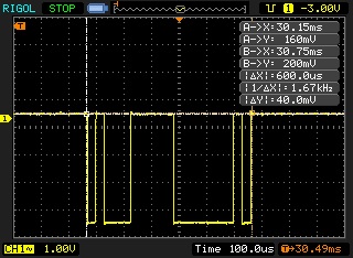
MIDI signal in oscilloscope. Inverted serial 31200 bits per second. Captured from USB->MIDI adapter (SWIS). First bit time is about 32us (31.2us = microsecond ). Voltage difference was 3.92V.

A great page describing MIDI: http://www.tigoe.net/pcomp/code/serial-communication/midi which describes MIDI like:
“MIDI is a serial communications protocol, operating at 31,250 bits per second. Each byte has 8 bits, plus a start bit and a stop bit. It operates at 5 volts DC. The standard MIDI connector is a 5-pin DIN connector, and usually all connectors on the device are female, and both ends of a MIDI cable are male.”
From here http://home.roadrunner.com/~jgglatt/tech/midispec.htm :
- MIDI is an asynchronous serial interface.
- The baud rate is 31.25 Kbaud (+/- 1%).
- There is 1 start bit, 8 data bits, and 1 stop bit (ie, 10 bits total), for a period of 320 microseconds per serial byte.
- The MIDI circuit is current loop, 5 mA.
- Logic 0 is current ON.
- To avoid grounding loops and subsequent data errors, the input is opto-isolated. It requires less than 5 mA to turn on. The Sharp PC-900 and HP 6N138 optoisolators are satisfactory devices. Rise and fall time for the optoisolator should be less than 2 microseconds.
- The standard connector used for MIDI is a 5 pin DIN.
- Separate jacks (and cable runs) are used for input and output, clearly marked on a given device (ie, the MIDI IN and OUT are two separate DIN female panel mount jacks).
- 50 feet is the recommended maximum cable length.
- Cables are shielded twisted pair, with the shield connecting pin 2 at both ends.
- The pair is pins 4 and 5. Pins 1 and 3 are not used, and should be left unconnected.
